|
Delphi 3D Designer - Felix John COLIBRI. |
- abstract : drawing 3D shapes and changing the camera and screen position with the mouse
- key words : 3D graphics, geometry, perspective, floodfill, vector graphics, camera, World view, homogeneous transforms
- software used : Windows XP, Delphi 6
- hardware used : Pentium 1.400Mhz, 256 M memory, 140 G hard disc
- scope : Delphi 1 to 8 for Windows, Kylix
- level : all developers
- plan :
1 - Introduction
I needed to draw some figures in 3D for code reengineering (module dependency graphs and the like). I had 2 choices: - use any OpenGL or other wonderful, but huge, tool
- grab my old DOS 3D program, and adapt it to Delphi.
I chose the last solution, and present here the whole library allowing to draw 3D figures. The main addition is the control of the point of view parameters with the mouse. Here is an example of the program with the project of our kitchen furniture:
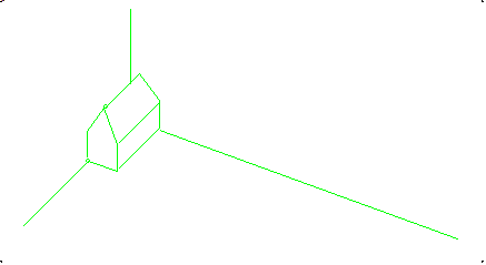
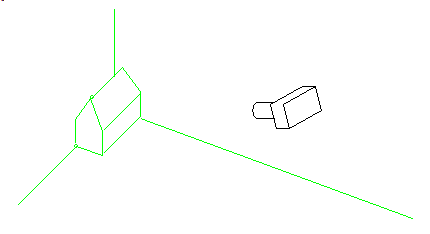
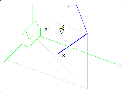
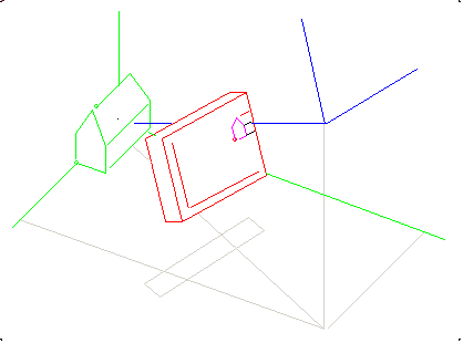
3D Geometry Let us take the simple example of a small house. Here is our house in world coordinates:
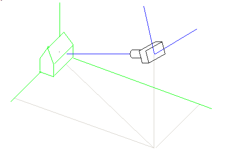
We look at this home using a camera, which is places somewhere in the world: To represent this home, we place a screen between the camera and the origin of the World:
We want to compute the screen coordinates of each point in the World.
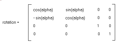
2.1 - Homogeneous coordinates To derive the projection formulas, we will use homogeneous coordinates.
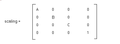
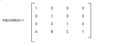
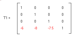
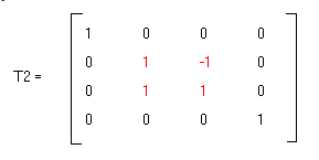
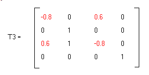
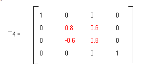
Transforms are computed using 4 by 4 matrices, where the last row is used to compute translation. The matrices of the 3 basic transforms are - scaling
- rotation around the vertical axis:
- translation
If we apply successive transforms, we simply multiply the corresponding matrices.
2.2 - 2d projection
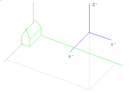
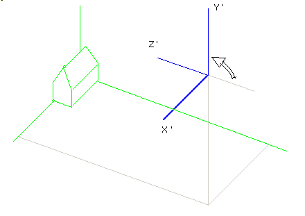
Let us assume that the camera is at position (6, 8, 7.5): Here are the transforms which will bring the World coordinates into the Camera coordinates:
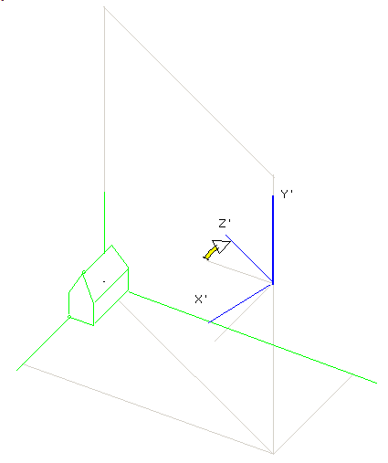
The complete change of axes is then T1* T2* T3* T4
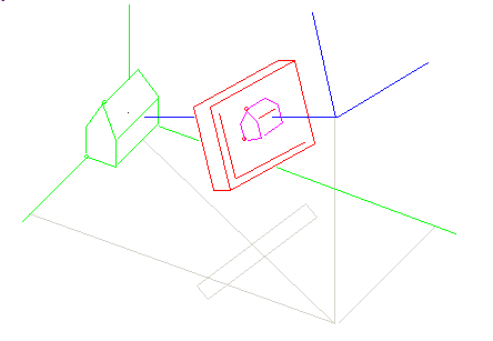
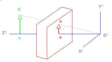
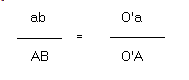
Finally we place the screen at different distance from the camera: and here is the formula:
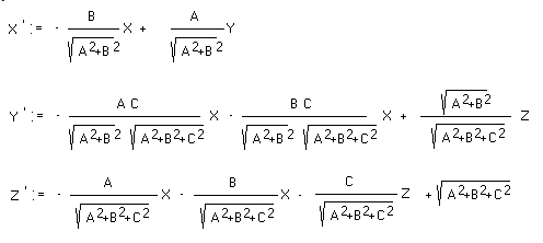
2.3 - The Transform formulas Using matrix multiplication is correct, but indexing matrices is very costly. So it is quicker to use the corresponding formulas. Replacing our litteral
values with variables, and with the following notations - X Y Z are the World coordinates
- ABC is the camera position
- X' Y' Z' are the screen values
Here are the formulas for the change of axes:
2.4 - Hidden faces Our old program used full Gouraud / Phong shading. Since this was not the most important point, we decided to use simple floodfill for the coloring of our
scene. So a place surface is declared visible if the cross product of the origin-to-camera vector with the normal to the surface is negative
3 - The Mouse Control 3.1 - Camera position control To set and change the camera position, we first started with usual tEdit. Once
the program was working, this quickly became tedious, so we tried to use mouse control.
Using 3 tTrackbars for the X, Y, Z camera position is easy, but not very
satisfying for change of the result. The rotations are more intuitive.
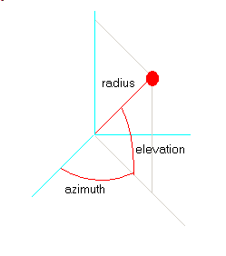
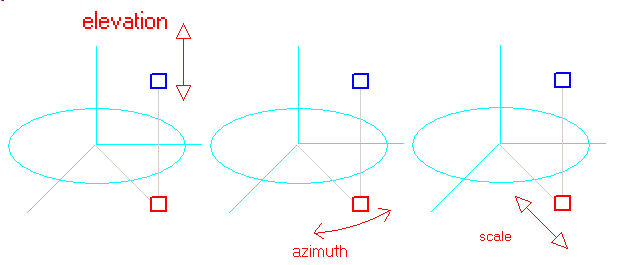
So the next trial was to use 3 parameters: - azimuth which is the angle in the xOy plane
- elevation, which is the angle in the vertical plane
- radius, which is the distance between the camera and the origin
Conversion of an (azimuth, elevation, radius) system to the (x, y, z) system is quite easy.
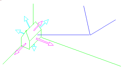
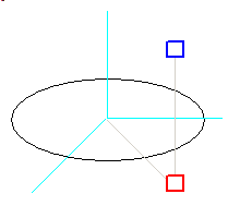
The previous system requires 3 different mouse controls. We tried to use fewer controls, trying to represent the camera in a 3d space (on our flat screen). To achieve this, we represented the axes in perspective in a combo box, and added
- an ellipse in perspective, representing the unit cylinder
- the camera with its projection on the xOy plane
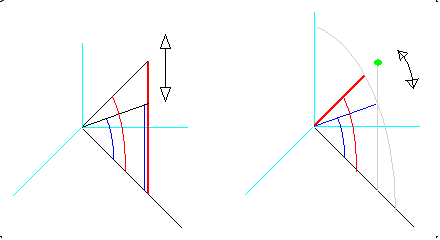
and changing the camera position is done by moving the 2 resizing plots: The most difficult part was to keep the elevation constant when changing the
azimuth or the scale. In addition, changing the elevation also changes the distance of the camera to the origin, and therefore the size of the result is modified. Here is the difference between the "spherical" and the "projection" approaches:
We kept the 2 mouse control in the Delphi code, but we more often use the classic 3 controls adjustments.
3.2 - Screen position control
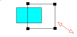
The screen position is controlled by another visual component, which represents the position of the screen in the camera system. Here is this control:
3.3 - Object movements Once all 3d drawings were correct, we tried to use the mouse to move several objects around.
The objects are placed in a list. An object is selected when the mouse is clicked inside the object's screen representation. We will not be able to reach nested objets, but those objects will also not be visible.
We tried here also to move object with 2D mouse movements, but this did not work very well. We assumed that comparing the mouse direction with the 3 axes could yield the direction closes to the mouse movement. However the mouse
events are usually fired for each 1 or 2 pixels movements, and for those distances, angle computations are not accurate. Accumulating several movements could be a solution. Or waiting for an initial accumulation of 5 or 10 pixels,
and after the direction selection, allow 1 pixel sensibility. In the project below, we settled for a separate direction movement: - the user selects the direction with x, y and z tRadioButtons
- the mouse is moved around
- the object is moved in this direction proportionally to the mouse movements
Even with this simplification, moves are not ideal: the mouse moves in projection space, and the objects are in 3d, with different scale. So we still
have to match somehow the screen distance with the 3d distance.
4 - the Delphi Source Code 4.1 - The vector library
To represent points, lines, surfaces and volume, we use records with (X, Y, Y) coordinates. The main question is whether we should use simple records, or CLASSes. I
first started with CLASSes, and whenever some geometric computations had to be performed, the objects had to be created with a CONSTRUCTOR and freed after the use. This is not necessary with simple records, and if they are local
variables, the stack nicely does all the housecleaning. Here is an example with the computation of the cosine of two vectors. We have three points: the origin, and the two points. Here are some possibilities:
- when we use CLASSes, the computation could look like this
procedure compute(p_x_a, p_y_b, p_x_b, p_y_b: Double);
var l_c_a, l_c_b: c_2d_point;
begin
l_c_a:= c_2d_point.create_2d_point(p_x_a, p_y_a);
l_c_b:= c_2d_point.create_2d_point(p_x_b, p_y_b);
l_c_a.normalize; l_c_b.normalize;
l_cosine:= f_cross_product(l_c_a, l_c_b);
l_c_a.Free; l_c_b.Free;
// -- ...
end; // compute
|
- using RECORDs, since Delphi FUNCTIONs can return RECORDs (and not only pointers to RECORDs like Standard Pascal) the style could be:
procedure compute(p_x_a, p_y_b, p_x_b, p_y_b: Double);
var l_a, l_b: t_2d_point;
begin
l_a:= f_2d_point(p_x_a, p_y_a);
l_b:= f_2d_point(p_x_b, p_y_b);
l_a:= f_2d_normalize(l_a); l_b:= f_2d_normalize(l_b);
l_cosine:= f_cross_product(l_a, l_b);
// -- ...
end; // compute
| or even:
procedure compute(p_x_a, p_y_b, p_x_b, p_y_b: Double);
begin
l_cosine:= f_cross_product(
f_2d_normalize(f_2d_point(p_x_a, p_y_a)),
f_2d_normalize(f_2d_point(p_x_b, p_y_b)));
// -- ...
end; // compute
|
Since in this application we did a lot of angle computations, normals, directions etc, we decided to use RECORDs with the functional style. We kept the CLASSes to handle the structuring of elements (lists of points, segments, surfaces etc)
4.2 - The 3D point UNIT Our UNIT has the following INTERFACE:
type t_2d_point= record
m_x, m_y: Double;
end; // t_2d_integer_point
t_pt_2d_point= ^ t_2d_point;
function f_2d_point(p_x, p_y: Double): t_2d_point;
function f_zero_2d_point: t_2d_point;
function f_2d_cross_product(const pk_2d_point_1, pk_2d_point_2: t_2d_point): Double;
function f_2d_norm(const pk_2d_point: t_2d_point): Double;
function f_normalize_2d_point(const pk_2d_point: t_2d_point): t_2d_point;
function f_2d_cosine(const pk_2d_point_1, pk_2d_point_2: t_2d_point): Double;
function f_2d_swap_xy(const pk_2d_point: t_2d_point): t_2d_point;
function f_2d_on_same_side(const pk_2d_line_point_1, pk_2d_line_point_2, pk_2d_point_1, pk_2d_point_2: t_2d_point): Boolean;
function f_add_2d_point(const pk_2d_point_1, pk_2d_point_2: t_2d_point): t_2d_point;
function f_subtract_2d_point(const pk_2d_point_1, pk_2d_point_2: t_2d_point): t_2d_point;
function f_multiply_2d_point_by_scalar(const pk_2d_point: t_2d_point; p_double: Double): t_2d_point;
function f_2d_are_identical(const pk_2d_point_1, pk_2d_point_2: t_2d_point): boolean;
function f_2d_are_aligned(const pk_2d_point_1, pk_2d_point_2, pk_2d_point_3: t_2d_point): boolean;
function f_display_2d_point(const pk_2d_point: t_2d_point): String;
function f_rotate_2d_point(p_2d_point: t_2d_point; p_angle: Double): t_2d_point;
procedure draw_2d_point(p_2d_point: t_2d_point; p_c_canvas: tCanvas; p_pen_color, p_radius: Integer);
|
4.3 - The 2D UNIT In a similar fashion, the 3d version is:
type t_3d_point= record
m_x, m_y, m_z: Double;
end; // t_3d_point
function f_3d_point(p_x, p_y, p_z: Double): t_3d_point;
Function f_3d_clone(const pk_3d_point: t_3d_point): t_3d_point;
function f_zero_3d_point: t_3d_point;
procedure reset_3d_point(var pv_3d_point: t_3d_point);
Function f_3d_cross_product(const pk_3d_point_1, pk_3d_point_2: t_3d_point): Double;
function f_3d_external_product(const pk_3d_point_1, pk_3d_point_2: t_3d_point): t_3d_point;
Function f_3d_point_norm(const pk_3d_point: t_3d_point): Double;
function f_normalize_3d_point(const pk_3d_point: t_3d_point): t_3d_point;
Procedure normalize_3d_point(var pv_3d_point: t_3d_point);
function f_add_3d_point(const pk_3d_point_1, pk_3d_point_2: t_3d_point): t_3d_point;
function f_subtract_3d_point(const pk_3d_point_1, pk_3d_point_2: t_3d_point): t_3d_point;
function f_multiply_3d_point_by_scalar(const pk_3d_point: t_3d_point; p_double: Double): t_3d_point;
function f_3d_are_identical(const pk_3d_point_1, pk_3d_point_2: t_3d_point): boolean;
function f_3d_are_aligned(const pk_3d_point_1, pk_3d_point_2, pk_3d_point_3: t_3d_point): boolean;
function f_display_3d_point(const pk_3d_point: t_3d_point): String;
|
4.4 - The Perspective CLASS Each time that we change the camera or the screen positions, we have to recompute the transform parameters. So is rather natural to encapsulate those
computations in a CLASS, and save the results in attributes. This CLASS will be handed over to the point lists of our scene. Since the CLASS will be used for all drawing, we also included attributes needed for the drawing: the
tCanvas, the drawing parameters (do fill the facet with colors or not, draw the facet normals etc.) Here is the CLASS definition:
c_perspective=
Class(c_basic_object)
m_c_canvas_ref: tCanvas;
m_3d_camera: t_3d_point;
s_11, s_12, s_13, s_21, s_22, s_23, s_32, s_33, s_43: Double;
_m_screen_width, _m_screen_height: integer;
_m_screen_center_x, _m_screen_center_y: integer;
// -- for the axis display
m_3d_origin: t_3d_point;
m_2d_origin: t_2d_integer_point;
// -- options
m_draw_color: Boolean;
m_draw_normal: Boolean;
constructor create_perspective(p_name: String; p_c_canvas: tCanvas);
procedure initialize_screen_position(p_center_x, p_center_y,
p_width, p_height: integer);
procedure initialise_camera_position(p_camera_x,
p_camera_y, p_camera_z: Double; p_scale: Double);
function f_project_3d_point(const pk_3d_point: t_3d_point): t_2d_point;
function f_project_3d_point_integer(const pk_3d_point: t_3d_point): t_2d_integer_point;
procedure draw_3d_segment(pk_3d_point_1, pk_3d_point_2: t_3d_point;
p_color: Integer);
procedure draw_2d_point(const pk_2d_point: t_2d_point; p_pen_color: Integer);
procedure draw_3d_point(const pk_3d_point: t_3d_point; p_pen_color: Integer);
Procedure draw_unit_axes(p_color: Integer);
end; // c_perspective
| and here is the transform computation:
procedure c_perspective.initialise_camera_position(p_camera_x,
p_camera_y, p_camera_z: Double; p_scale: Double);
// -- compute the transformation coefficients
var l_xy_radius, l_radius, l_d23: Double;
begin
l_xy_radius:= Sqrt(Sqr(p_camera_x)+ Sqr(p_camera_y));
l_radius:= Sqrt(Sqr(p_camera_x)+ Sqr(p_camera_y)+ Sqr(p_camera_z));
l_d23:= l_xy_radius* l_radius;
s_11:= - p_camera_y* p_scale/ l_xy_radius;
s_12:= - p_camera_x* p_camera_z* p_scale/ l_d23;
s_13:= - p_camera_x/ l_radius;
s_21:= p_camera_x* p_scale/ l_xy_radius;
s_22:= - p_camera_y* p_camera_z* p_scale/ l_d23;
s_23:= - p_camera_y/ l_radius;
s_32:= l_xy_radius* p_scale/ l_radius;
s_33:= - p_camera_z/ l_radius;
s_43:= l_radius;
normalize_3d_point(m_3d_camera);
end; // initialise_point_de_vue
| with the associated computation of a point projection:
function c_perspective.f_project_3d_point(const
pk_3d_point: t_3d_point): t_2d_point;
Var l_x_t, l_y_t, l_z_t: Double;
begin
l_z_t:= pk_3d_point.m_x* s_13
+ pk_3d_point.m_y* s_23+ pk_3d_point.m_z* s_33+ s_43;
l_x_t:= (pk_3d_point.m_x* s_11+ pk_3d_point.m_y* s_21)/ l_z_t;
l_y_t:= (pk_3d_point.m_x* s_12
+ pk_3d_point.m_y* s_22+ pk_3d_point.m_z* s_32)/ l_z_t;
// -- simple translation / scaling for screen
Result.m_x:= 1.0* _m_screen_center_x+ l_x_t* _m_screen_width;
Result.m_y:= 1.0* _m_screen_center_y- l_y_t* _m_screen_height;
end; // f_project_3d_point
|
4.5 - The Screen controller
This CLASS will allow the user to resize and move the screen representation. Basically, it includes a tPaintBox (since we must draw rectangles) and mouse events. Usually, we have two options:
- either drop the tPaintBox on the tForm, and delegate the events to the tForm
- or build a component and place it on the Palette
The first solution is a one shot implementation. Building a component is easy,
but requires reinstallation when we change PC's, Windows or Delphi version. So we prefer a third solution where the most possible is encapsulated in a CLASS which is simple included in the main UNIT. To do so
- we build the c_screen_controller CLASS, complete with then paint and mouse events
- the CONSTRUCTOR receives a container (a tPanel) creates a tPaintbox
inside of this container, and initialize the events of this tPaintBox
- when the user clicks the mouse, the events are directly forwarded to this CLASS. We eventually prepare notifications to the user, if required.
The user of this CLASS simply specifies which tPanel will contain the controller, and uses the notifications to update the display or interrogates the CLASSe's attributes for other processings. So this is like a component,
but without the installation procedure (and without the Object Inspector facilities).
Here is the definition of the c_screen_controller:
t_notify_change= Procedure;
c_screen_controler= class(c_basic_object)
m_c_parent_panel_ref: tPanel;
m_c_paintbox: tPaintBox;
m_base_ratio: Double;
m_scale_start_x, m_scale_start_y: Integer;
m_scale_end_x, m_scale_end_y: Integer;
m_ratio_height, m_ratio_width: Double;
m_ratio_x, m_ratio_y: Double;
// -- the fixed figure representing the screen
m_base_x, m_base_y: Integer;
m_base_width, m_base_height: Integer;
// -- for moving (Right click)
m_mouse_x, m_mouse_y: Integer;
m_on_notify_change: t_notify_change;
Constructor create_screen_controler(p_name: String;
p_c_parent_panel_ref: tPanel;
p_base_ratio: Double;
p_ratio_width, p_ratio_height: Double;
p_ratio_x, p_ratio_y: Double;
p_handle_scaler_change: t_notify_change);
function f_display_scale: String;
function f_display_ratios: String;
procedure draw_rectangle(p_scale_end_x, p_scale_end_y: Integer);
procedure handle_paint(Sender: TObject);
procedure handle_mouse_down(Sender: TObject;
p_mouse_button: TMouseButton;
p_shift_state: TShiftState; p_x, p_y: Integer);
procedure handle_mouse_move(Sender: TObject;
p_shift_state: TShiftState; p_x, p_y: Integer);
Destructor Destroy; Override;
end; // c_screen_controler
|
4.6 - The Azimuth / Elevation / Scale control The CLASS representing the camera class plays exactly the same role, but for handling the 2 point camera control. This CLASS is defined as:
t_procedure= Procedure(p_before: Boolean);
c_camera_controler= Class(c_basic_object)
m_c_paintbox_ref: tPaintBox;
_m_c_canvas_ref: tCanvas;
// -- optimization: avoid recalculations
m_2d_integer_origin: t_2d_integer_point;
m_2d_origin: t_2d_point;
m_2d_origin_x, m_2d_origin_y: t_2d_point;
// -- the "unit" circle (half the paintbox)
m_unit_width, m_unit_height: Integer;
// -- the mouse in the world xy plane
m_2d_azimuth: t_2d_point;
// -- the mouse in the vertical
m_2d_elevation: t_2d_point;
m_azimuth, m_elevation, m_scale_ratio: Double;
// -- when arrives in Oz // Omouse
m_last_known_elevation: Double;
m_is_azimuth, m_is_elevation: Boolean;
m_on_change_controler: t_procedure;
constructor create_camera_controler(p_name: String;
p_c_paintbox_ref: tPaintBox;
p_controler_ratio: Double;
p_on_change_controler: t_procedure);
function f_azimuth_angle(p_x, p_y: Double): Double;
function f_elevation_angle(p_x, p_y: Double): Double;
Procedure draw_unit_axes(p_color: Integer);
procedure draw_all(p_color: Integer);
procedure update_controler(p_x, p_y: Integer);
procedure handle_mouse_down(Sender: TObject;
p_mouse_button: TMouseButton;
p_shift_state: TShiftState; p_x, p_y: Integer);
procedure handle_mouse_move(Sender: TObject;
p_shift_state: TShiftState; p_x, p_y: Integer);
procedure initialize_position;
Destructor Destroy; Override;
end; // c_camera_controler_controler
|
With the 2d and 3d point units, the perspective primitives and the camera / screen controllers, we are able to build a 2d projection of any 3d vector
graphic scene. We will illustrate the use of our units with a block world.
4.7 - Line, Surface, Volume, Scene Our figure elements use - the point RECORDs presented above
- those records are placed in c_vertex CLASS (for on the fly computations, RECORDs are used, but for container storage, CLASSes are better)
c_3d_vertex= // one "3d_vertex"
Class(c_basic_object)
m_vertex_id: integer;
m_3d_point: t_3d_point;
constructor create_3d_vertex(p_name: String; p_3d_point: t_3d_point);
function f_display_3d_vertex: String;
function f_c_self: c_3d_vertex;
procedure translate_3d_vertex(p_3d_delta: t_3d_point);
end; // c_3d_vertex
| - the 3D poly line (not necessary a planar shape) defined as a tStringlist of c_vertex
c_3d_vertex_list= // "3d_vertex" list
Class(c_basic_object)
_m_c_3d_vertex_list: tStringList;
m_is_closed: Boolean;
Constructor create_3d_vertex_list(p_name: String);
function f_3d_vertex_count: Integer;
function f_c_3d_vertex(p_3d_vertex_index: Integer): c_3d_vertex;
function f_index_of(p_3d_vertex_name: String): Integer;
function f_c_find_by_3d_vertex(p_3d_vertex_name: String): c_3d_vertex;
procedure add_3d_vertex(p_3d_vertex_name: String;
p_c_3d_vertex: c_3d_vertex);
function f_c_add_3d_vertex(p_3d_vertex_name: String;
p_3d_point: t_3d_point): c_3d_vertex;
procedure display_3d_vertex_list;
function f_vertex_list_names: String;
procedure draw_vertex_list(p_c_perspective: c_perspective;
p_pen_color: Integer);
procedure translate_3d_vertex_list(p_3d_delta: t_3d_point);
Destructor Destroy; Override;
end; // c_3d_vertex_list
| - the planar surfaces, delimited with a border poly-line are defined by the c_facet CLASS
c_facet= // one "facet"
Class(c_basic_object)
m_c_3d_vertex_list: c_3d_vertex_list;
m_normal_sign: Integer;
m_3d_normal: t_3d_point;
m_facet_color: Integer;
Constructor create_facet(p_name: String; p_normal_sign: Integer);
function f_display_facet: String;
function f_c_self: c_facet;
procedure compute_normal;
procedure draw_facet(p_c_perspective: c_perspective;
p_pen_color: Integer);
function f_3d_normal_end: t_3d_point;
function f_is_2d_point_in_2d_facet(p_2d_point: t_2d_point;
p_c_perspective: c_perspective): boolean;
procedure translate(p_dx, p_dy, p_dz: Double);
procedure translate_facet(p_3d_delta: t_3d_point);
Destructor Destroy; Override;
end; // c_facet
| Note that - c_facet and c_vertex list are nearly identical, and one of them could
be removed (or the c_facet could be a planar c_vertex_list descendent). In our case, we consider the c_facet as a planar c_vertex_list, with a m_3d_normal vector, and this is the reason why we kept those separate.
- the normal is build using the first 3 points. We assume they are not aligned (no check).
- the sign is introduced to orient the facets (clock wise or anti clock wise), and this is specified at creation time
- the volume are built from c_facets and are handled with the c_facet_list CLASS
c_facet_list= // "facet" list
Class(c_basic_object)
m_c_facet_list: tStringList;
Constructor create_facet_list(p_name: String);
function f_facet_count: Integer;
function f_c_facet(p_facet_index: Integer): c_facet;
function f_index_of(p_facet_name: String): Integer;
function f_c_find_by_facet(p_facet_name: String): c_facet;
procedure add_facet(p_facet_name: String; p_c_facet: c_facet);
function f_c_add_facet(p_facet_name: String;
p_normal_sign: Integer): c_facet;
procedure display_facet_list;
function f_c_self: c_facet_list;
procedure compute_facet_normals;
procedure draw(p_c_perspective: c_perspective;
p_pen_color: Integer);
function f_is_selected(p_2d_mouse: t_2d_point;
p_c_perspective: c_perspective): Boolean;
procedure translate(p_dx, p_dy, p_dz: Double);
procedure translate_facet_list(p_3d_delta: t_3d_point);
procedure display_unique_facet_list;
procedure set_position(p_3d_position: t_3d_point);
Destructor Destroy; Override;
end; // c_facet_list
| - several volumes are managed with a c_volume_list
c_volume_list= // "volume" list
Class(c_basic_object)
m_c_volume_list: tStringList;
Constructor create_volume_list(p_name: String);
function f_volume_count: Integer;
function f_c_volume(p_volume_index: Integer): c_facet_list;
function f_index_of(p_volume_name: String): Integer;
function f_c_find_by_volume(p_volume_name: String): c_facet_list;
procedure add_volume(p_volume_name: String; p_c_volume: c_facet_list);
function f_c_add_volume(p_volume_name: String): c_facet_list;
procedure display_volume_list;
procedure draw(p_c_perspective: c_perspective; p_pen_color: Integer);
procedure add_cube(p_cube_name: String);
procedure add_pyramid(p_pyramid_name: String);
procedure add_horizontal_plane(p_plane_name: String);
procedure add_vertical_x0z_plane(p_plane_name: String);
procedure add_vertical_y0z_plane(p_plane_name: String);
function f_c_find_selected_volume(p_2d_mouse: t_2d_point;
p_c_perspective: c_perspective): c_facet_list;
Destructor Destroy; Override;
end; // c_volume_list
| and the volumes are build by separate functions like this cube:
function f_c_cube(p_name: String;
p_3d_origin, p_3d_x, p_3d_y, p_3d_z: t_3d_point): c_facet_list;
var l_3d_A, l_3d_B, l_3d_C, l_3d_D,
l_3d_E, l_3d_F, l_3d_G, l_3d_H: t_3d_point;
begin
l_3d_A:= p_3d_origin;
l_3d_B:= f_add_3d_point(l_3d_A, p_3d_y);
l_3d_C:= f_add_3d_point(l_3d_B, p_3d_z);
l_3d_D:= f_add_3d_point(l_3d_A, p_3d_z);
l_3d_F:= f_add_3d_point(l_3d_B, p_3d_x);
l_3d_G:= f_add_3d_point(l_3d_C, p_3d_x);
l_3d_H:= f_add_3d_point(l_3d_D, p_3d_x);
l_3d_E:= f_add_3d_point(l_3d_A, p_3d_x);
Result:= c_facet_list.create_facet_list(p_name);
with Result do
begin
with f_c_add_facet('face1', - 1), m_c_3d_vertex_list do
begin
f_c_add_3d_vertex('A', l_3d_A);
f_c_add_3d_vertex('B', l_3d_B);
f_c_add_3d_vertex('C', l_3d_C);
f_c_add_3d_vertex('D', l_3d_D);
end; // with f_c_add_facet
with f_c_add_facet('face2', 1), m_c_3d_vertex_list do
begin
f_c_add_3d_vertex('B', l_3d_B);
// -- ... C G F
end; // with f_c_add_facet
// -- front
with f_c_add_facet('face3', - 1), m_c_3d_vertex_list do
// -- ... G F E H
// -- top
with f_c_add_facet('face4', 1), m_c_3d_vertex_list do
// -- ... H G C D
compute_facet_normals;
end; // with p_c_facet_list
end; // f_c_cube
|
Notice that we did not build the 8 faces, since we mainly displayed the scene with the camera in the first quadrant (x, y, z >= 0). Using the 3 spherical tTrackbar, those movements are not limited though (we can view
the scene from "behind", or even "below") - the volume list, the perspective, and the final display are enclosed in a c_scene CLASS, where all mouse selection and movements in the block display are handled:
t_direction= (e_unknown_direction, e_x_direction, e_y_direction, e_z_direction);
t_notify_change= Procedure;
c_scene= class(c_basic_object)
m_c_scene_paintbox_ref: tPaintBox;
m_c_volume_list_ref: c_volume_list;
m_c_perspective_ref: c_perspective;
m_direction: t_direction;
m_on_selection_change_event: t_notify_change;
m_c_selected_volume: c_facet_list;
Constructor create_scene(p_name: String;
p_c_scene_paintbox_ref: tPaintBox;
p_c_volume_list_ref: c_volume_list;
p_c_perspective_ref: c_perspective;
p_on_selection_change_event: t_notify_change);
procedure set_direction(p_direction: t_direction);
procedure handle_paint(Sender: TObject);
procedure handle_mouse_down(Sender: TObject;
p_mouse_button: TMouseButton;
p_shift_state: TShiftState; p_x, p_y: Integer);
procedure handle_mouse_move(Sender: TObject;
p_shift_state: TShiftState; p_x, p_y: Integer);
Destructor Destroy; Override;
end; // c_scene
|
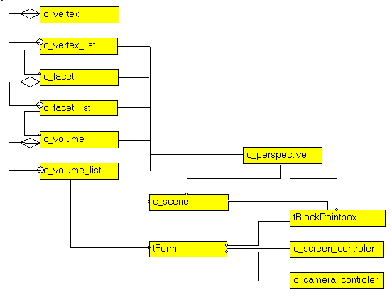
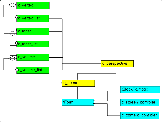
4.8 - UML Class diagram
The UML diagram of this graphic library is the following: The nice thing about UML diagrams is that they highlighte possible
reorganizations. In our case, the main tForm was used to check compilation of each CLASS. Then references of some CLASSes were placed in container CLASSes and the structure was constructed in a progressive fashion. But the
diagram shows that: - we could get rid of the g_c_volume_list in the main tForm, and let the c_scene regroup all volumes
- this is also true for the g_c_perspective global variable
4.9 - Building the Scene We then added a Palette with some standard volumes (a cube, a pyramid, and 2 planes. The mouse then is used to move those blocks around.
4.10 - The result Here is a snapshot of the final application, with a couple of cubes: 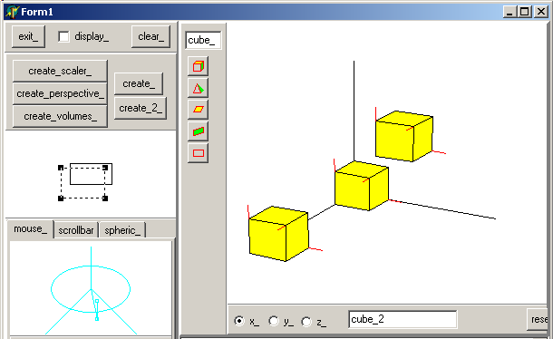 If we want to see at which hight the block are, we place the camera at ground
level (xOy): 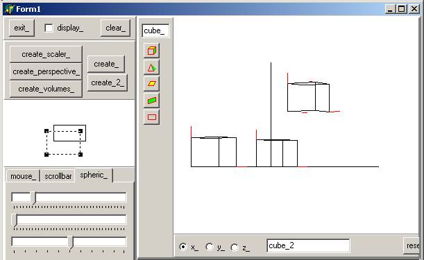 Notice that we removed coloring to accelerate the movements (floodfill is very slow). The movement was performed using the spherical controls. And here is a
top-view, after centering the figure with the screen controller, and without the optional red normals 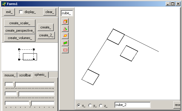
4.11 - Mini HowTo To use the project
- compile
- create the screen controller, camera controler and an empty volume list by clicking "create_"
- add a object by clicking the "cube" speed button (or the "pyramid" ...)
- select a direction ("x_", "y_", "z_") and move the object away from the origin by dragging the mouse
- change the scaling or centering by using the screen control
- change the camera position using either the 2 point representation or the
spherical 3 trackbars
5 - Improvements This tools was build to solve a specific problem (3d representation and easy camera / screen movement). So the volume part is not optimized in any way. We
could improve, or add: - an object designer, which could be used:
- to build other shapes than those already defined
- to modify an object (move the vertices, the facets, add facets etc)
- add other volume movements than translations (rotations, scaling)
- on the representation side
- use different coloring (gouraud, phong)
- for object management
- add load and save (streaming)
- add object hierarchies
- use some scripting language to build the scene
- using this textual representation, implement constraints
- on the control side
6 - Download the Sources Here are the source code files:
Those .ZIP files contain: - the main program (.DPR, .DOF, .RES), the main form (.PAS, .DFM), and any other auxiliary form
- any .TXT for parameters
- all units (.PAS) for units
Those .ZIP
- are self-contained: you will not need any other product (unless expressly mentioned).
- can be used from any folder (the pathes are RELATIVE)
- will not modify your PC in any way beyond the path where you placed the .ZIP
(no registry changes, no path creation etc).
To use the .ZIP: - create or select any folder of your choice
- unzip the downloaded file
- using Delphi, compile and execute
To remove the .ZIP simply delete the folder.
As usual: - please tell us at fcolibri@felix-colibri.com if you found some errors, mistakes, bugs, broken
links or had some problem downloading the file. Resulting corrections will be helpful for other readers
- we welcome any comment, criticism, enhancement, other sources or reference
suggestion. Just send an e-mail to fcolibri@felix-colibri.com.
- or more simply, enter your (anonymous or with your e-mail if you want an
answer) comments below and clic the "send" button
- and if you liked this article, talk about this site to your fellow
developpers, add a link to your links page ou mention our articles in your blog or newsgroup posts when relevant. That's the way we operate: the more traffic and Google references we get, the more articles we will write.
7 - Conclusion This project presents a 3d perspective library which can be used for individual point 2d representations, or to build more complex object scenes
8 - The author
Felix John COLIBRI works at the Pascal Institute. Starting with Pascal in 1979, he then became involved with Object Oriented Programming, Delphi, Sql, Tcp/Ip, Html, UML. Currently, he is mainly
active in the area of custom software development (new projects, maintenance, audits, BDE migration, Delphi
Xe_n migrations, refactoring), Delphi Consulting and Delph
training. His web site features tutorials, technical papers about programming with full downloadable source code, and the description and calendar of forthcoming Delphi, FireBird, Tcp/IP, Web Services, OOP / UML, Design Patterns, Unit Testing training sessions.
|